×
单片机编程就是c语言 寄存器设置。
以前对pic振荡器的配置都是拿来主义,把别人的代码拿过来用就行了。这两天特意研究下振荡器的配置与时钟切换。在mplab ide和c30编译器下,针对pic24fjxx系列单片机完成的测试。
配置振荡器最主要的目的就是为了设置机械时钟fosc,此时钟给cpu和外设提供时钟源。但为了降低功耗又不中断外设正常通信,此系列pic保证cpu与外设的时钟同步情况下,增加了打盹模式,用于降低cpu运行时钟速度,以达到节能效果。
个人是这么理解的,cpu时钟就是代码运行时钟,决定代码运行速度;外设时钟就是中断、定时器、输入捕捉、输出比较、uart、spi等外设的时钟源。 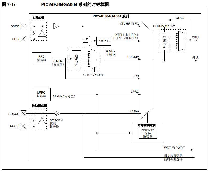
在时钟框图中可看出,由四个振荡器提供时钟源,包括两个外部振荡器(主振荡器、辅助振荡器)和两个内部振荡器(frc振荡器——快速rc、lprc振荡器——低功耗rc)。
时钟模式共11种:
1. xt——1m到4m的石英晶体振荡器(主振荡器)
2. hs——超过4m的石英晶体振荡器(主振荡器)
3. ec——低于1m的陶瓷振荡器(主振荡器)
4. xtpll——带pll模块的主振荡器(主振荡器)
5. hspll——带pll模块的主振荡器(主振荡器)
6. ecpll——带pll模块的主振荡器(主振荡器)
7. frcpll——带后分频器和pll模块的快速rc振荡器(内部振荡器)
8. frcdiv——带后分频器的快速rc振荡器(内部振荡器)
9. frc——快速rc振荡器(内部振荡器)
10. lprc——低功耗rc振荡器(内部振荡器)
11. sosc——辅助振荡器(辅助振荡器)
注:①pll模块是一个锁相环(phase lock loop)倍频器,可提高4倍频率,②这里共有11时钟模式,在配置时,有一个保留模式,但无hspll模式
一般为了减少外围电路,采用内部振荡器,其时钟频率最高可达32m。如果需要严格的时钟频率,而内部振荡器又无法匹配上,那才考虑外部振荡器。所以一般按以下步骤来配置(后面对应寄存器名):
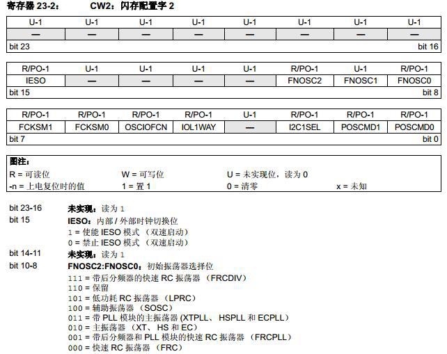
1. 是否使用主振荡器——配置位cw2的poscmd1:poscmd0
2. 选择初始振荡器,即时钟模式——配置位cw2的fnosc2:fnosc0
3. 配置osco引脚功能,在ec和非主振荡器时钟模式下,不占用此引脚,可配置成fosc/2时钟输出clko,或普通i/o口ra3——配置位cw2的osciofcn
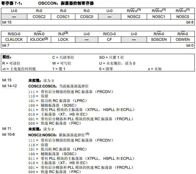
4. 【不使用sosc模式可忽略此步】配置sosc辅助振荡器使能位——osccon的soscen
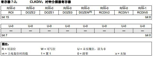
5. 【不使用frcpll、frcdiv模式可忽略此步】配置frc后分频比——clkdiv的rcidv2:rcdiv0
6. 【不使用打盹模式可忽略此步】配置cpu与外设的时钟比——clkdiv的doze2:doze0
7. 【不使用打盹模式可忽略此步】配置中断是否影响打盹使能位(dozen)——clkdiv的rio
8. 【不使用打盹模式可忽略此步】使能打盹模式——clkdiv的dozen
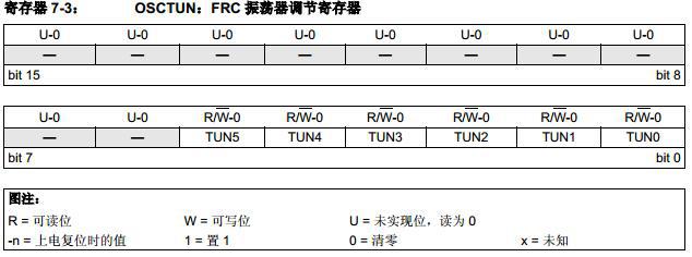
9. 【不调节frc振荡器频率,应忽略此步】校准frc振荡器频率——osctun的tun5:tun0
(四个寄存器位组成参考文章末尾)
在不使用时钟切换的模式下,以上9步就可解决振荡器的配置问题。上面涉及到4个寄存器cw2、osccon、clkdiv和osctun,要配置他们可不是直接使用“_soscen = 1;”或“oscconbits.soscen = 1;”那样简单。clkdiv和osctun两个寄存器可按前面的方式进行配置,而cw2与osccon需要通过其他方式进行配置:
1)cw2——两种方法
可通过ide自带配置位界面(configure->configuration bits…)直接选择
或在#include包含文件位置后,使用代码_config2(value),value为配置数值,如:
_config2(poscmod_none & fnosc_frcpll & osciofnc_on & fcksm_csecme)
2)osccon——也有两种方法
首先说明下,osccon是个核心寄存器,不是可以随便编辑的,用了两把锁把它的高低字节分别锁起来了。所以要编辑它,必须先解锁。高字节osccon<15:8>写序列为:连续将78h和9ah写入高字节进行解锁,立即写入需要的数值。低字节osccon<7:0>写序列为:连续将46h和57h写入低字节进行解锁,立即写入需要的数值。
因此,要先区分所编辑位属于osccon高字节还是低字节,再按要求进行解锁和写入。
第一种方法,使用内置函数,__builtin_write_oscconh(value)来配置osccon高字节,和__builtin_write_oscconl(value)来配置osccon低字节。使用内置函数,不需要考虑解锁,编译成汇编代码已经包含了解锁序列,见下图(参考c30编译器的帮助文件hlpmplabc30.chm) 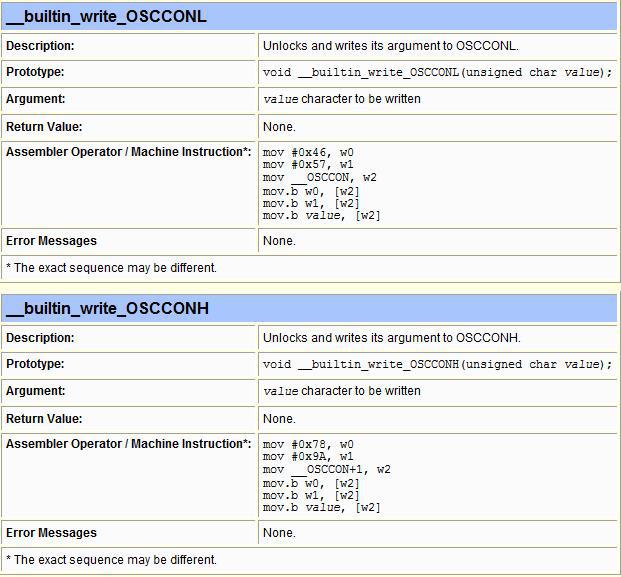
第二种方法,直接使用汇编语言,嵌套在c语言中。发现c30不支持#asm和#endasm的多行汇编,就使用单行嵌入“asm(instruction);”,望知道的大侠告诉一声(谢谢^_^)。
asm("mov #oscconh, w1");
asm("mov #0x78, w2");
asm("mov #0x9a, w3");
asm("mov #0x00, w4"); //0x00 is the value will write to oscconh
asm("mov.b w2, [w1]");
asm("mov.b w3, [w1]");
asm("mov.b w4, [w1]");
asm("mov #oscconl, w1");
asm("mov #0x46, w2");
asm("mov #0x57, w3");
asm("mov #0x01, w4"); //0x01 is the value will write to oscconl
asm("mov.b w2, [w1]");
asm("mov.b w3, [w1]");
asm("mov.b w4, [w1]");
相信用c语言写程序的人都会选内置函数。
以下是个完整的代码,使用frcpll时钟模式,fosc=32m,用定时器t1开关led灯,实现每3s切换一次状态:
#include
_config1(jtagen_off & gcp_off & fwdten_off)
_config2(poscmod_none & fnosc_frcpll & osciofnc_on) // clock mode:frcpll, osco/ra3 functions as port i/o
typedef char byte;
typedef unsigned int word;
typedef unsigned long int dword;
#define led_tris _trisa3
#define led_on() _lata3 = 1
#define led_off() _lata3 = 0
#define led_trigger() _lata3 = ~_lata3
#define time_ten_microsecond 300
word ledtriggercount = 0;
void ic_initialize(void)
{
/*oscillator configuration :32m frcpll*/
__builtin_write_oscconl(0x00);
clkdivbits.rcdiv = 0b000; //frc postscaler divide by 1, is 8m
/*enable doze mode*/
//clkdivbits.doze = 0b001;
//clkdivbits.dozen = 1; //enable doze bit
/*initialize t1*/
t1conbits.tcs = 0; // internal clock
t1conbits.tgate = 0; //disable gated time accumulation
t1conbits.tckps = 0b01; //prescale =1:8, t1 = 2*8/fosc = 0.5us
t1conbits.ton =0;
tmr1 = 0;
pr1 = 20000; // time on a cycle is 10us
_t1md = 0; //default value, enable clock source to t1
_t1ip = 7; //highest priority
_t1if = 0;
_t1ie = 1; //enable t1 interrupt
}
int main(void)
{
ic_initialize();
led_tris =0;
led_on();
t1conbits.ton =1; //t1 start
while(1);
return 0;
}
void __attribute__ ((__interrupt__, no_auto_psv)) _t1interrupt(void)
{
if( ledtriggercount == time_ten_microsecond){
ledtriggercount = 0;
led_trigger();
}
_t1if = 0;
}
二. 时钟切换
时钟切换按正常逻辑来理解,应该是告诉我一个新时钟模式,然后我切换过去就好了。对,就是这么简单。具体地寄存器操作步骤,看下面:
1. 开启时钟切换功能,fcksm1位必须清零——cw2的fcksm1:fcksm0
2. 配置新时钟模式——osccon的nosc2:nosc0
3. 开始切换——osccon的oswen
三步完成时钟切换,但有四点要注意:
1)主振荡器下的三个子模式(xt、hs和ec)是由配置位决定,他们之间无法切换的。这好理解,你用一台发电机给工厂发电,你要切换发电机,在不断电的情况下不好办吧,得先断电后再切换。这里要切换就要重新烧录程序并设置配置位
2)使能pll的主振荡器与frcpll之间也不能直接切换,但可通过先中转到frc下再切换
3)涉及到引脚或分频类的,要注意设置好,参考datasheet,这里不再赘述
4)osccon的cosc2:cosc0可读出当前时钟模式,在切换前可先判断当前时钟模式
下面实例代码,在frcpll(fosc=32m)和frc(fosc=8m)模式之间循环切换,通过led呈现状态结果。在frcpll模式下,led亮2s,灭2s,然后切换到frc模式下,亮8s,灭8s,再切换到frcpll模式下,如此循环:
#include
_config1(jtagen_off & gcp_off & fwdten_off)
_config2(poscmod_none & fnosc_frcpll & osciofnc_on & fcksm_csecme) // osco/ra3 functions as port i/o, enable clock switch
typedef char byte;
typedef unsigned int word;
typedef unsigned long int dword;
#define led_tris _trisa3
#define led_on() _lata3 = 1
#define led_off() _lata3 = 0
#define led_trigger() _lata3 = ~_lata3
#define time_ten_microsecond 200
word ledtriggercount = 0;
byte oscillatorswitchcount = 0;
void ic_clockswitch(byte newosc)
{
_t1ie = 0; //disable all interrupts before switching
__builtin_write_oscconh(newosc); //set new oscillator mode
__builtin_write_oscconl(0x01); //enable oscillator switch
while(oscconbits.oswen); //waiting for a successful clock transition
_t1ie = 1; //enable interrupt after switched
}
void ic_initialize(void)
{
//oscillator configuration :32m frcpll
clkdivbits.rcdiv = 0b000; //frc postscaler divide by 1, input 4*pll is 8m
clkdivbits.doze = 0b001; //1:2, cpu clock:16m
clkdivbits.dozen = 1; //enable doze bit
//initialize t1
t1conbits.tcs = 0; // internal clock
t1conbits.tgate = 0; //disable gated time accumulation
t1conbits.tckps = 0b01; //prescale =1:8, t1 = 2*8/fosc = 0.5us
t1conbits.ton =0;
tmr1 = 0;
pr1 = 20000; // time on a cycle is 10us
_t1md = 0; //default value, enable clock source to t1
_t1ip = 7; //highest priority
_t1if = 0;
_t1ie = 1; //enable t1 interrupt
}
int main(void)
{
ic_initialize();
led_tris =0;
led_on();
t1conbits.ton =1; //t1 start
while(1);
return 0;
}
void __attribute__ ((__interrupt__, no_auto_psv)) _t1interrupt(void)
{
if( ledtriggercount == time_ten_microsecond){
ledtriggercount = 0;
led_trigger();
if( oscillatorswitchcount == 2){
oscillatorswitchcount = 0;
ic_clockswitch(~oscconbits.cosc&0x01);//switch clock mode between frcpll and frc
}
}
_t1if = 0;
}
里面的代码“ic_clockswitch(~oscconbits.cosc&0x01);”与下面代码功能一样:
if(oscconbits.cosc == 0b001)
ic_clockswitch(0x00); //frcpll -> frc
else
ic_clockswitch(0x01); //frc -> frcpll
『本文转载自网络,u球体育app下载的版权归原作者所有,如有侵权请联系删除』


 热门文章
更多
热门文章
更多

 stm32问题记录:这回keil编译器背锅


 app下载
app下载